


Hydraulic calculations
When designing hydraulic systems, it is important to use correctly sized equipment that is appropriate for the application. Not only does this ensure the equipment is fit for purpose it will also prove cost effective.
Correctly applied calculations lay the foundations to an efficient and cost effective system. We have provided design engineers with a compact document that contains formulae required to calculate:
- Flow rate.
- Pressure.
- Power.
- Force.
- Torque.
- Pump displacement.
- Motor displacement.
- Oil velocity within a pipe.
- The Reynolds number.
By following the calculations laid out in this article, or using the online hydraulic calculators embedded within the Hydrastore website, you will quickly and accurately calculate each discrete parameter for your hydraulic system.
The basic equation of force is:
F (Force) = P (Pressure) x A (Surface Area).
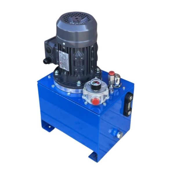
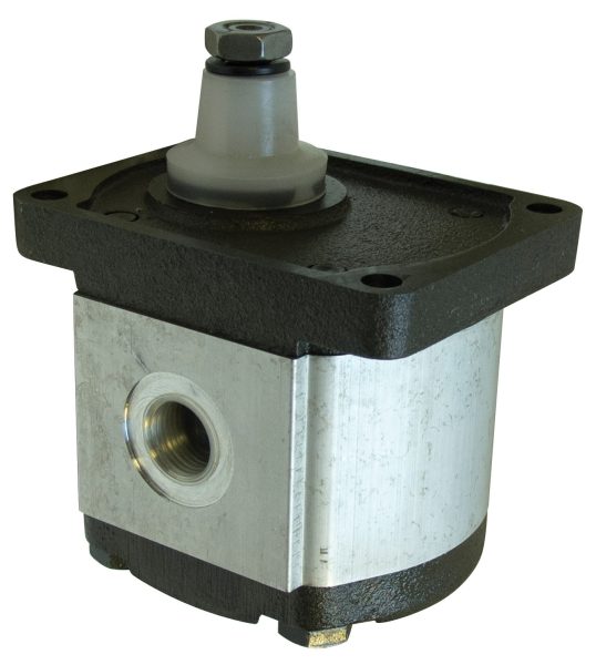
Hydraulic Pump and Motor Calculations
Determining the correct sized electric motor for your hydraulic system will aid in reducing energy consumption while increasing efficiency. Ensuring the motor is operating at peak continuous load is key, but knowing the exact power requirement is very important.
Flow and Pressure Relationship
Qα √ Δρ
i.e. if the flow is doubled the pressure drop increases in the ratio 4:1
Where:
Q = Flow Rate [L/min]
n = Shaft Speed [rev/min]
p = Pressure [bar]
P = Power [kW]
D = Displacement [cm³/rev]
F = Force [N]
v = Velocity [m/s]
T = Torque [Nm]
A = Area [cm²]
d = Pipe Diameter [mm]
Δρ = Pressure Drop (bar)
Useful Conversions
1 Litre = 1000 cm³
1 bar = 100000 Pa
1 bar = 14.5 psi
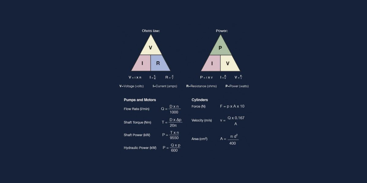
Fast track hydraulic formulae
Pumps and Motors
- Flow Rate (I/min)
- Q = (D x n) / 1000
- Shaft Torque (Nm)
- T = (D x Δρ ) / 20π
- Shaft Power (kW)
- P = (T x n) / 9550
- Hydraulic Power (kW)
- P = (Q x p) / 600
Cylinders
- Force (N)
- F = p x A x 10
- Velocity (m/s)
- v = (Q x 0.167) / A
- Area (cm²)
- A = (π d²) / 400
Note: component efficiencies need to be considered for a more precise analysis.
Hydraulic pipes and hoses formulae
- Velocity of fluid in pipe (m/s)
- v = (Q x 21.22) / d²
Where:
d = Pipe Diameter (mm)
Recommended fluid velocity ranges
- Suction lines
- 0.625m/s – 1.25m/s
- Pressure lines
- 2.1m/s – 4.75m/s
Based on oils having a maximum viscosity grade of 70 cSt at 38°C and operating between 18°C and 51°C.
Note: For pipe runs greater than 10m the pipe size should be increased correspondingly. The intake line should never exceed 1m in length.
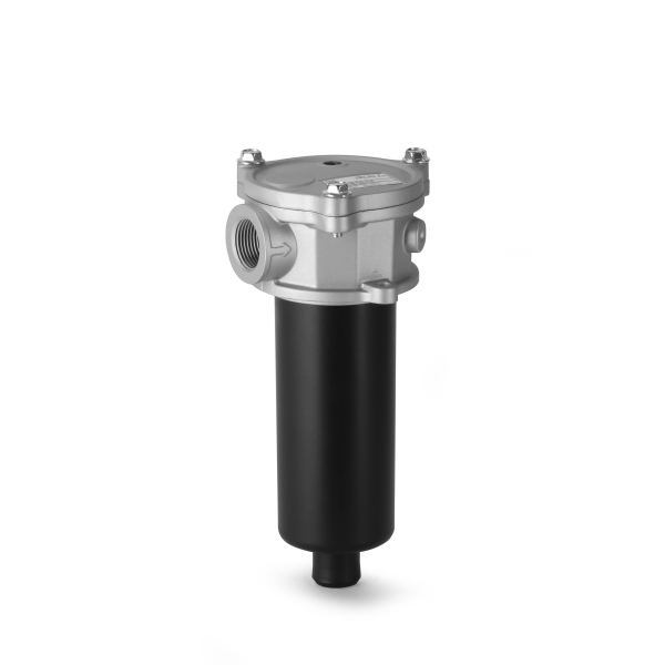
Flushing formulae
Flushing is a process designed to remove dirt introduced into the system during manufacture, assembly and initial operation. It is also used when significant maintenance is undertaken. The requirements are summarised below:-
- A turbulent flow regime to pick-up the particles from the walls of components and transport them to the flushing filter.
- The Reynolds number (Re) defines the flow condition and should be greater than 4,000 and can be calculated using:
- Reynolds Number
- (Re = 21,200 x Q) / (v x d)
- Or to achieve Re ≥ 4,000
Q > 0.189 x v x d
Where:
Q = Flow Rate (I/min)
v = Viscosity (cSt)
d = Pipe Diameter (mm)
Re = Reynolds Number
A ‘fine’ filter to capture transported particles quickly and effectively.
Electronics formulae
- Ohms law
- V = I x R
- I = V / R
- R = V / I
- Power
- P = I x V
- I = P / V
- V = P / I
V=Voltage (volts)
I=Current (amps)
R=Resistance (ohms)
P=Power (watts)
Principles of hydraulics (NFPC)
- Flow makes it go
- Pressure provides the pushing force
- Oil in a system always takes the path of least resistance
- Pressure is a measure of the resistance to flow
- For oil to flow there must always be a pressure difference
- The greater the pressure difference the greater the flow potential
- When oil flows from a high pressure to a low pressure without doing work, heat is generated
Pascal’s Law and Hydraulic Calculations
Pascal’s Law, or Pascal’s Principle as it is also known, was first established by French mathematician Blaise Pascal and published in 1663. It is a law that states, in fluid mechanics, pressure in one part of a closed container with fluid at rest transmits to every portion of the fluid and to the walls of the container, without loss.
Pressure is equal to the force divided by the area on which it acts. In a hydraulic system, the pressure exerted on a piston produces an equal increase in pressure on another piston in the system. The force on the second piston is 10 times greater if the area of the second piston is also 10 times that of the first. However, the pressure is the same as that on the first piston.
The hydraulic press is a perfect example of Pascal’s Principle in action and is also applied in the use of hydraulic brakes.
Pascal’s Principle Calculator
Hydraulic pumps are designed to produce a flow of fluid through the system. Pressure in the system occurs as a result of any resistance to the flow of the fluid. According to Pascal’s Law, cylinders within the system will all move at their own rate based on the weight of the load being moved. A calculation is needed to understand how far each cylinder will extend.
-
Latest Guides
- Hydraulic Systems: Principles, Components and How Hydraulics Power Modern Machinery 19 July 2026
- Types of Hydraulic Pumps Explained for Industrial Applications 27 May 2026
- Hydraulic Fluid Types: Choosing the Right Hydraulic Oil for Your System 22 April 2026
- Enclosure Design Checklist: Q&A with an Acoustics Supplier 18 February 2026
- Whats the real cost of contaminated hydraulic fluid? 18 February 2026
- The hidden costs of running a hydraulic power pack 18 February 2026
-
Recent News Articles
- Visit us at Hillhead 2026! 16 June 2026
- Celebrating 15 years of Partnership 3 March 2026
- Showcasing Innovation at LAMMA 2026 30 January 2026
- We’re Exhibiting at Dairy-Tech on Wednesday 4th February 30 January 2026
- New Exclusive Partnership: CEI Hydraulic Manifolds 30 January 2026
- Maddison Foreman Joins DCA 30 January 2026