


Hydraulic Systems: Principles, Components and How Hydraulics Power Modern Machinery
A practical guide to hydraulic systems, including principles, components, circuits, pressure, flow and common engineering issues.
Hydraulic systems sit at the centre of most heavy machinery used across construction, manufacturing and transport. Excavators digging foundations, cranes lifting structural steel, presses forming components and dump trucks tipping loads all rely on a hydraulic system to generate force and control movement.
Most engineers encounter hydraulics long before they formally study it. A machine slows down. A cylinder begins drifting. A pump runs hotter than expected. Somewhere in the circuit, pressure, flow or fluid condition is no longer behaving as the system design assumed.
That’s the nature of hydraulics. The underlying theory is simple. The practical behaviour of a working system — especially after thousands of operating hours — is where real engineering judgement comes in.
At its core, a hydraulic system converts mechanical input energy into hydraulic energy using a hydraulic pump. Pressurised hydraulic fluid then moves through a controlled circuit of valves and pipework before reaching an actuator such as a hydraulic cylinder or hydraulic motor.
This guide explains the basic principles of hydraulic systems, the major components of a hydraulic circuit, and where engineers typically focus when designing, specifying, or troubleshooting hydraulic equipment.
What Is Hydraulics?
Hydraulics refers to the engineering discipline that uses liquids to transmit and control power.
Most hydraulic systems rely on oil-based fluids that behave as nearly incompressible fluids. That property allows pressure to transfer efficiently through a circuit.
The principle behind hydraulic systems comes from the work of Blaise Pascal, whose experiments in fluid mechanics demonstrated that pressure applied to a confined fluid spreads equally throughout that fluid.
Engineers recognise this as Pascal’s Law.
The principle states that when pressure applied to one part of a confined fluid changes, that same change occurs throughout the system. This behaviour allows hydraulic systems to multiply force. Increasing the surface area of an output piston increases the resulting force.
That concept underpins every hydraulic machine, from small workshop presses to large equipment used in construction and industrial processing. Machines that commonly rely on hydraulics include: Excavators, Bulldozers, Loaders, Cranes, Dump trucks, Industrial press machinery. Hydraulics fall within the broader field of fluid power, in which energy is transmitted through liquids rather than through mechanical gear trains.
How a Hydraulic System Works
Although hydraulic machines vary in layout, most hydraulic systems follow the same operating cycle.
A typical hydraulic circuit contains:
- A hydraulic pump
- A reservoir
- Control valves
- An actuator, such as a hydraulic cylinder or hydraulic motor
The process begins when the hydraulic pump draws hydraulic fluid from the reservoir through the pump inlet. This usually occurs by creating a vacuum at the inlet. Atmospheric pressure then pushes fluid into the pump chamber.
Mechanical movement inside the pump forces fluid into the system. As the fluid flow encounters resistance within the hydraulic circuit, fluid pressure develops. Control components determine where that pressure travels.
A directional control valve routes fluid to the required actuator. A relief valve protects the system from excessive pressure. When the fluid reaches the actuator, hydraulic energy is converted back into mechanical motion. Once the fluid has delivered its energy, it returns to the reservoir, where it cools before circulating through the system again.
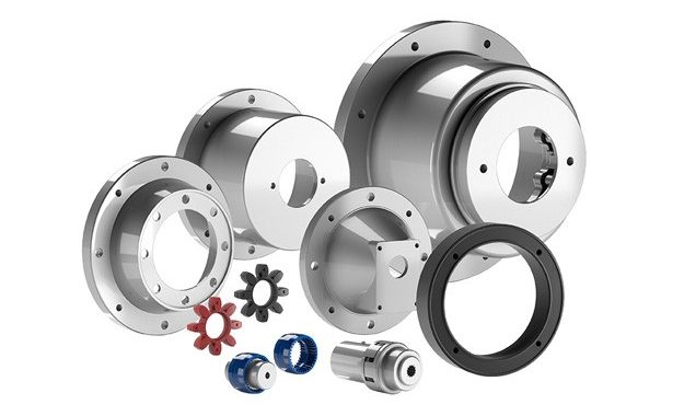
Hydraulic Cylinders
A hydraulic cylinder produces linear motion. Pressurised fluid pushes a piston inside the cylinder barrel, extending or retracting the rod. This motion allows machines to lift, push or clamp loads.
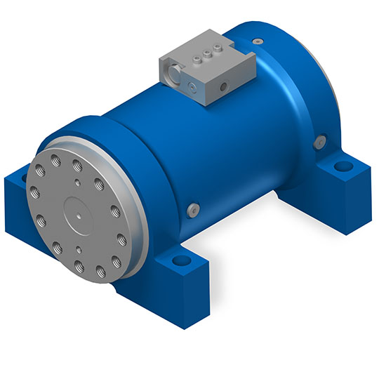
Hydraulic Motors
A hydraulic motor converts pressure and flow into rotational movement. Internal gears, vanes or pistons rotate a shaft and generate torque. Hydraulic motors are commonly used in wheel drives, conveyors and rotating equipment.
What Is a Hydraulic Circuit?
A hydraulic circuit describes the arrangement of components that control fluid movement within a hydraulic system. The simplest hydraulic circuit normally contains:
- Reservoir
- Hydraulic pump
- Pressure relief valve
- Directional control valve
- Actuator
- Return line
Fluid flows continuously through this circuit while the system operates. In more complex machines, the circuit may include additional components, such as accumulators, flow control valves, and multiple actuators. Understanding the hydraulic circuit layout is usually the first step in diagnosing performance issues.
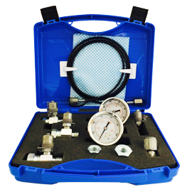
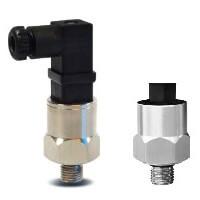
Pressure, Flow and Hydraulic Power
Two variables largely determine hydraulic system performance: pressure and flow.
System Pressure
Pressure represents the force potential within the hydraulic circuit. It is commonly measured in pounds per square inch (psi) or bar. Higher pressure allows actuators to generate greater force. Lifting cylinders on construction equipment, for example, operate under high-pressure conditions in order to move heavy loads.
Hydraulic Flow
Flow refers to the amount of fluid moving through the system. It determines actuator speed and is usually measured in gallons per minute or litres per minute.
Hydraulic Power
The relationship between pressure and flow determines the available hydraulic power. High pressure with limited flow produces large force but slower motion. High flow increases actuator speed but does not increase force unless pressure rises.
Hydrastore Engineering Insight
When reviewing hydraulic equipment, one issue appears regularly: systems designed with excessive pressure capacity but insufficient flow. The machine still operates, but actuator movement slows more than expected, and heat generation within the system increases. Correct pump sizing and flow calculations usually resolve the issue.
Key Components Within a Hydraulic System
A complete hydraulic system relies on several integrated components. Each one influences efficiency, reliability and maintenance requirements.
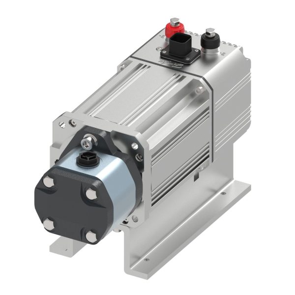
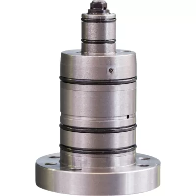
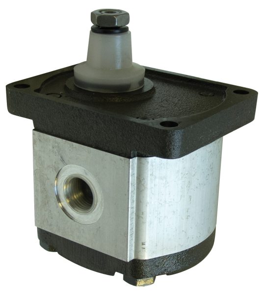
Hydraulic Pumps
The hydraulic pump generates the fluid flow required to move hydraulic energy through the system. Pumps do not directly create pressure. Pressure occurs when fluid flow meets resistance in the circuit. Common types of hydraulic pumps include:
- Gear pumps
- Vane pumps
- Piston pumps
Gear pumps are widely used in mobile machinery due to their simple design. Piston pumps are common in high-pressure industrial systems. Pumps may operate as fixed displacement pumps or variable displacement pumps, allowing system flow to adjust to demand.
Discover the types of hydraulic pumps Hydrastore stocks
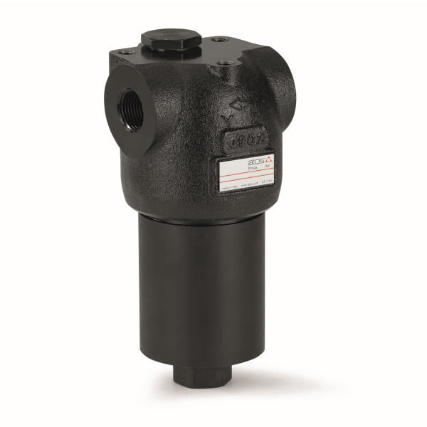
Hydraulic Fluid
Hydraulic fluid serves as the medium for energy transmission.
It must perform several tasks simultaneously:
- Transmit energy
- Lubricate moving components
- Remove heat
- Carry contaminants toward filtration systems
Fluid cleanliness plays a major role in system life. Even small levels of fluid contamination can damage pumps, motors and valves.
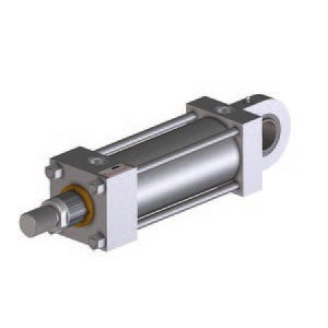
Hydraulic Cylinders
A hydraulic cylinder converts fluid pressure into linear mechanical force. Pressurised oil pushes a piston connected to a rod, producing the motion required to lift or move loads.
Cylinders may be:
- Single acting
- Double acting
- Telescopic
Telescopic cylinders are commonly used in dump truck tipping systems where a long extension stroke must fit within limited installation space.
The different types of hydraulic cylinders
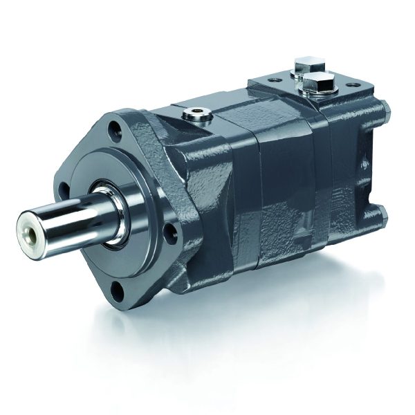
Hydraulic Motors
A hydraulic motor converts hydraulic energy into rotational movement. Motor designs include:
- Gear motors
- Gerotor motors
- Vane motors
- Axial piston motors
- Radial piston motors
Motor speed depends on fluid flow, while output torque depends on system pressure.
Check out our Hydraulic Motor Sizing Guide
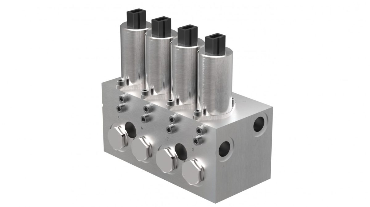
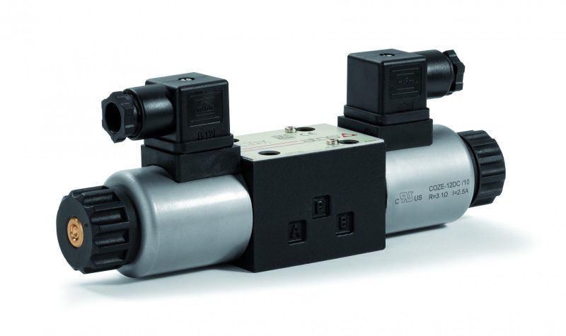
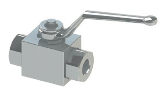
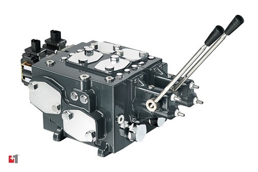
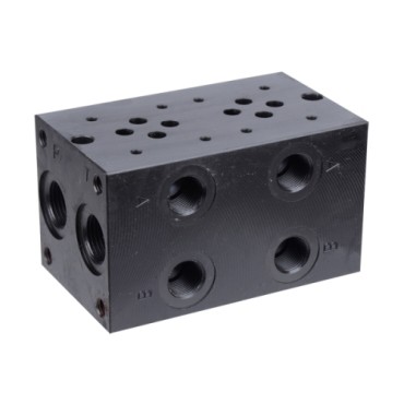
Valves and Control Systems
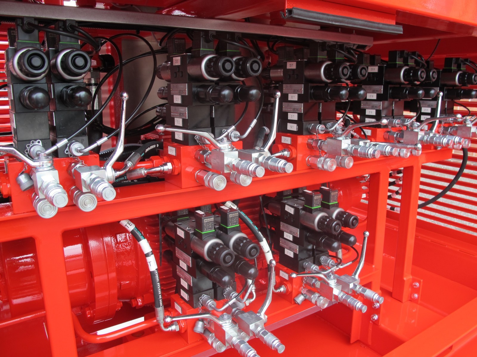
Valves control how fluid moves through the hydraulic circuit. Key valve types include:
- Directional control valves
- Pressure relief valves
- Flow control valves
Correct valve selection allows machines to achieve precise control over actuator movement.
See our Hydraulic Valve Types Guide – coming soon
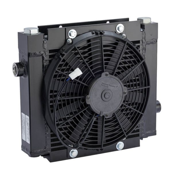
Reservoirs and Accumulators
The reservoir stores hydraulic fluid and allows returning fluid to cool before recirculating.
Some systems include a hydraulic accumulator, which stores hydraulic energy in compressed gas and fluid. Accumulators help stabilise system pressure during sudden load changes.
Types of Hydraulic Systems
Several different types of hydraulic systems are used in engineering applications.
Open Loop Systems
Fluid flows from the pump through valves and actuators before returning to the reservoir. This configuration is common in mobile hydraulic machinery.
Closed Loop Systems
Fluid circulates directly between pump and motor without returning to the reservoir each cycle. Closed loop circuits are widely used in hydrostatic transmission systems.
Hydraulics vs Mechanical Transmission
Hydraulic systems differ from mechanical transmission systems in several ways.
| Feature | Hydraulic Systems | Mechanical Systems |
| Force output | Very high | Limited by gear size |
| Motion control | Smooth and adjustable | Fixed ratios |
| Component size | Compact for force produced | Often larger |
These advantages explain why hydraulics remain dominant in many forms of heavy machinery.
Common Hydraulic System Problems
Even well-designed systems can develop issues over time.
Slow actuator movement
Often caused by restricted flow, blocked filters or incorrect pump sizing.
Excessive heat
Usually linked to pressure losses, inefficient pumps or continuous relief valve operation.
Cylinder drift
Commonly caused by internal seal leakage or valve leakage.
Pump cavitation
Occurs when the pump inlet cannot supply enough fluid, causing vapour bubbles to form inside the pump.
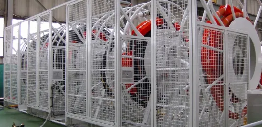
Hydraulic Applications in Industry
Hydraulics appear across many industries.
Construction machines such as excavators, bulldozers, loaders and cranes rely heavily on hydraulic systems.
In transport equipment, hydraulics operate tipping mechanisms in dump trucks and transmit braking force within vehicle brake systems.
Industrial sectors use hydraulics in press machinery, automated production equipment, and heavy industrial processes, such as in paper mills.
Designing Reliable Hydraulic Systems
Reliable hydraulic system design requires careful component selection and system configuration.
Key considerations include:
- Correct hydraulic pump sizing
- Matching actuator capacity to load requirements
- Managing pressure and flow
- Preventing fluid contamination
- Maintaining stable operating temperatures
Incorrect sizing of pumps, valves or actuators can reduce efficiency and accelerate wear.
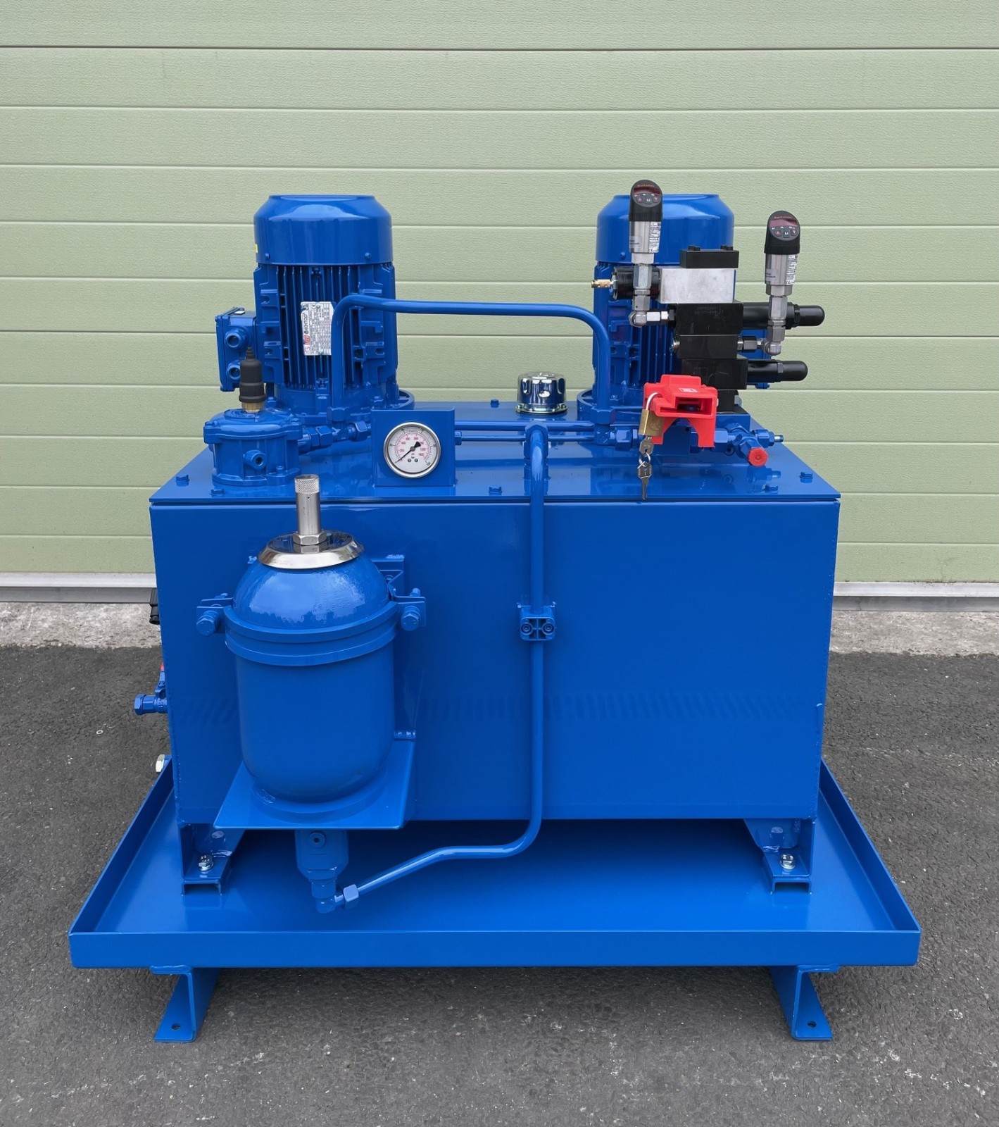
Hydraulic System Design Support
Hydrastore works with engineers and equipment manufacturers across the UK to support hydraulic system design, specification and troubleshooting.
Our engineering team regularly assists with:
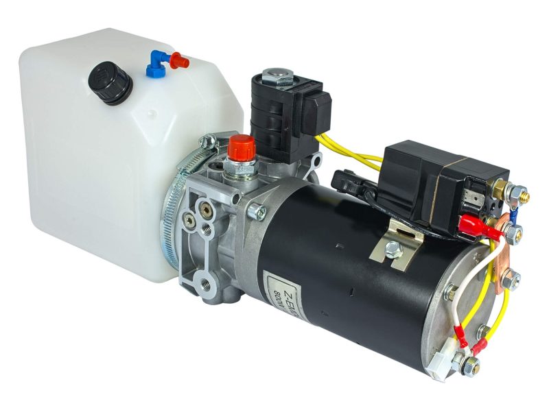
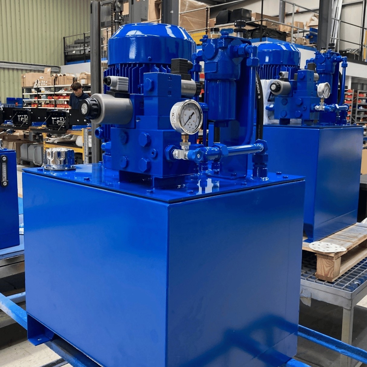
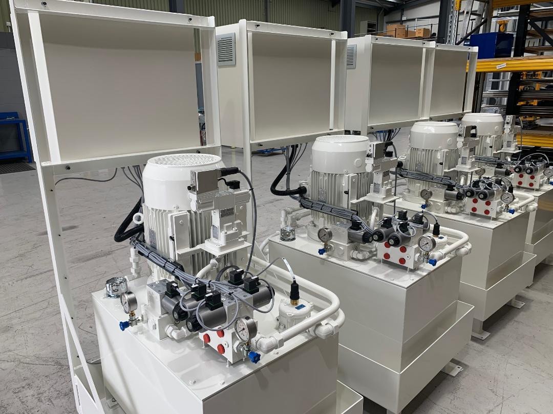
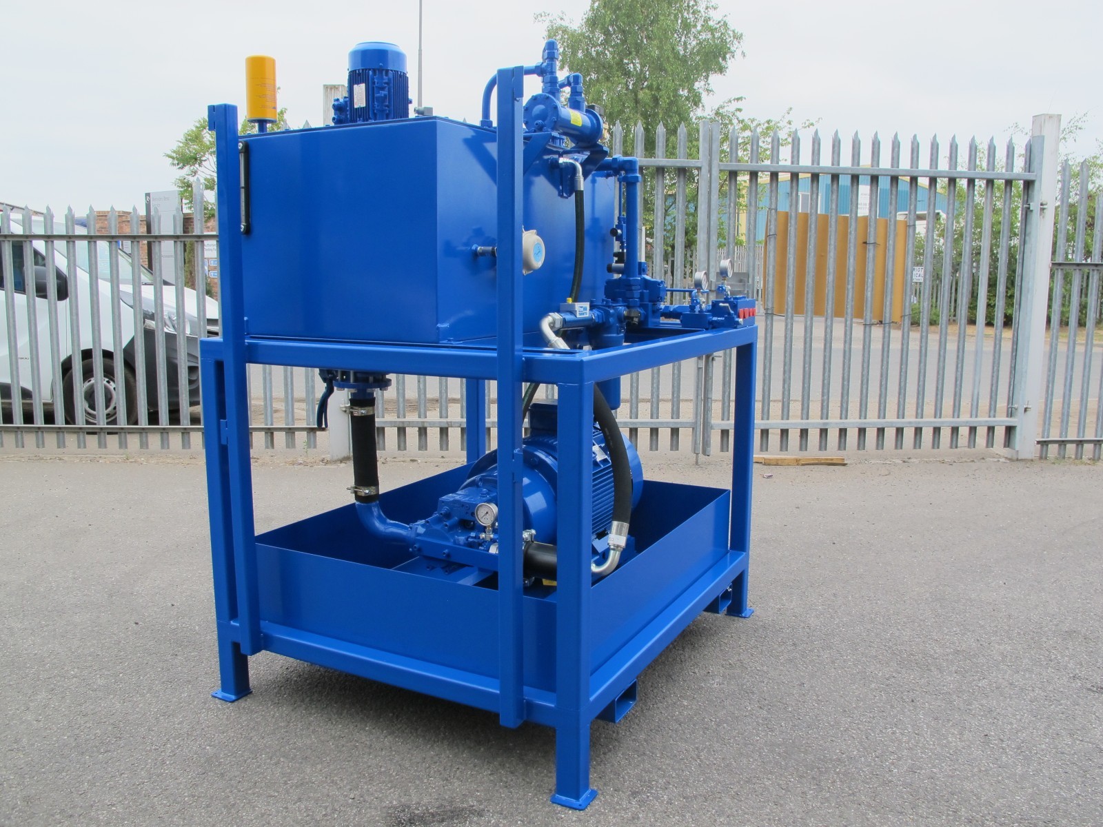
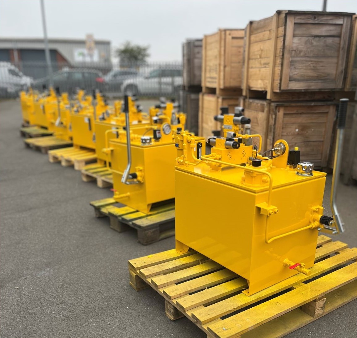
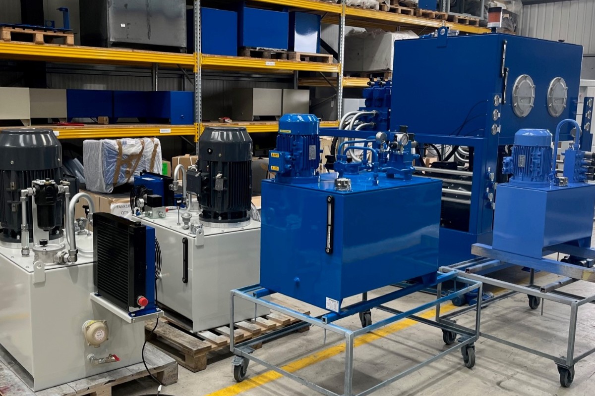
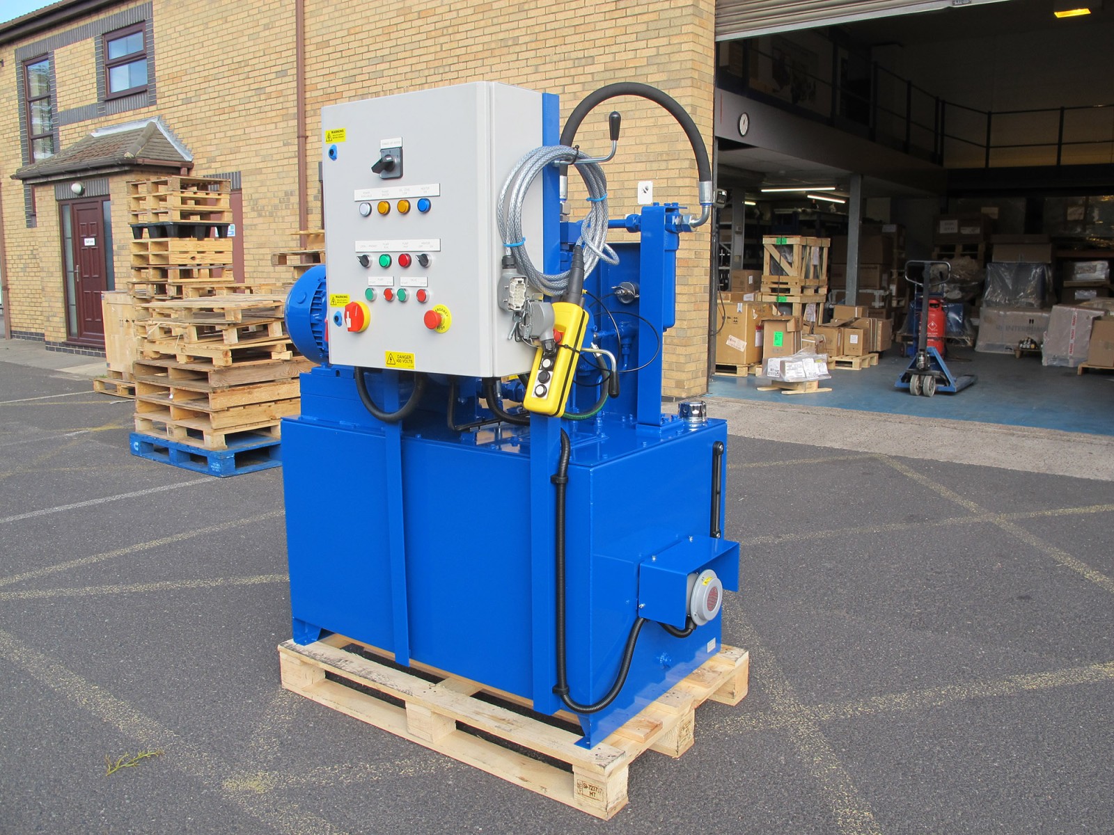
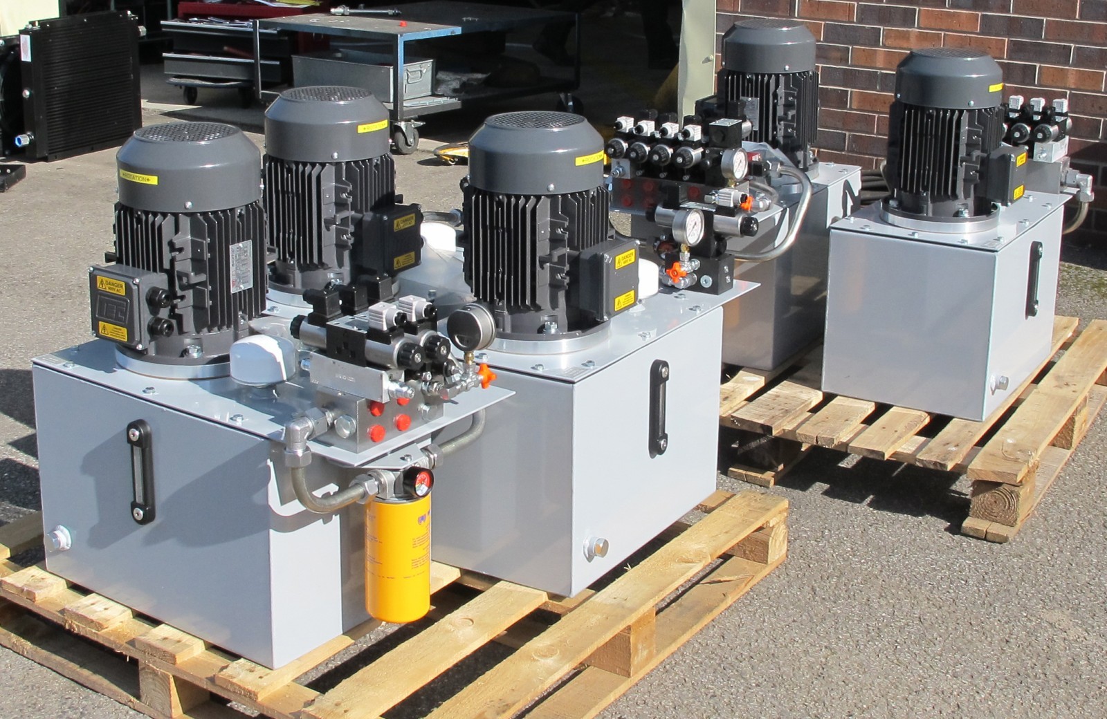
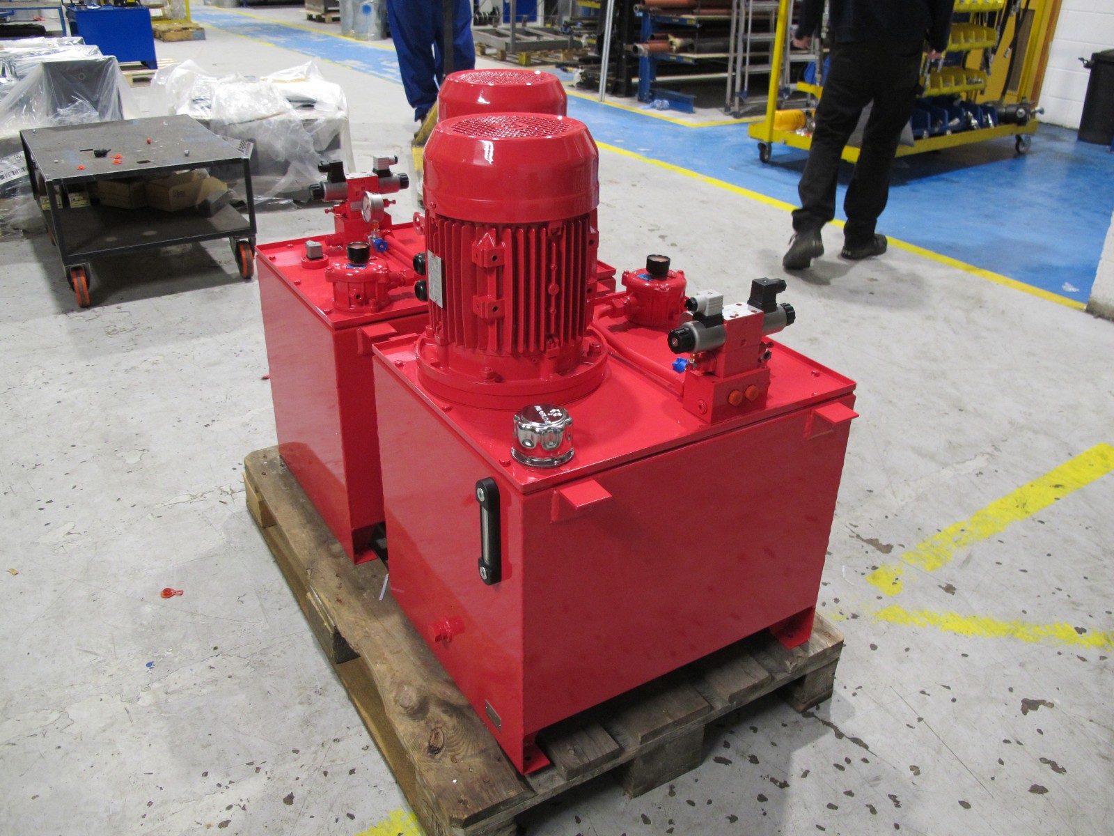
- Hydraulic power unit design
- Pump and actuator selection
- Hydraulic system calculations
- Diagnosing performance issues in hydraulic equipment
If you are planning a new hydraulic project or reviewing an existing machine, our engineers can help ensure your hydraulic systems operate efficiently and reliably.
Whether you need advice, support, or want to start a project – we’re ready to help.
Whether you’re sourcing a single component or planning a large-scale system build, our team has the technical expertise to support you. From hydraulics and electrification to radio systems and advanced electronic control solutions—or fully integrated combinations—we work with you to deliver precisely engineered outcomes. Whatever the scope or complexity, we provide informed, reliable guidance to help you achieve optimal performance and efficiency.
Common Questions
Industrial hydraulic systems typically operate between 150 and 350 bar, depending on the application.
Hydraulic oils compress very little under normal operating pressure, allowing energy to transmit efficiently through the system.
Heat is produced when energy is lost through pressure drops, fluid friction or inefficient component operation.